|
|
Features of the Onguard FG8800 Fire and Gas System
- The system is scalable to meet increasing demands of the industry.
- Designed for annunciating and agent release.
- All configurations and reports are stored on non-volatile flash memory.
- A standard USB port is utilized to backup configurations and reports.
- System files are transferable to other FG8800 panels utilizing the same node configurations to duplicate installations.
- The complete system is configured utilizing all ready known Windows commands.
- The color TFT display is responsible for accepting all alarm silencing and reporting by a touch of the finger.
- The TFT display can be ordered in two different viewing angles.
- The node communication bus utilizes a shield twisted pair and can sometimes accommodate the 24V power on smaller installations.
- Configurations are built one-at-a-time and tested individually to allow simplicity as the system increases in scale.
- Each configuration can be individually “loaded” or “unloaded” to disable a function if required .
- Configuration choices are available for gas, instant release, timed release, water mist, dual release and other options.
- The input node can vote between channels.
- The input node can issue a warning if a detector enters into alarm and the voting requirement is not attained.
- Gas node accommodates three set points.
- Optional diagnostic test software allows testing of each node independently.
- Dual release mode allows a second release to occur if the pressure switch does not change state or the if fire continues.
- The learning process for the system requires no schooling. Individuals can read through the manual to learn how to operate the program and operational procedures.
- The systems visual simplicity invites users to quickly learn and program alarm events.
- Heavy duty relays are utilized on the relay node and supervisory output module.
|
|
|
|

Addressable Industrial Fire/Gas Panel
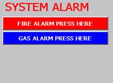
Allestec introduces another high performance gas/fire panel that is addressable, scaleable and extremely reliable. The system is normally operated in a standby mode as indicated in the picture above. Incoming alarms trip field nodes and respond to configurations created utilizing the included software. Alarm silencing and resetting can be accomplished through the touch screen display.
Programming is implemented through a Windows selection screen allowing user friendly operational commands. A USB mouse and VGA monitor are temporarily connected to the control panel to program the system.
Configurations are created as task specific individual entities and are saved in a configuration folder. The configurations can be unloaded if they are not to be included in an alarm condition. A configuration can be edited or deleted as the user requires.
The FG8800 GAS/FIRE panel is mounted in a 19” EIA rack or panel mounted. The control panel is designed for industrial operations but may be included in commercial applications.
Four different style of field nodes are capable of connecting all the initiating, notification and releasing devices. The standard system can support 128 nodes (4 channels/node) with options to expand to 2048. The two output modules provide heavy duty rating relays.
Protocols include a standard Modbus port to allow users to remotely acquire data. A TCP/IP optional interface is available for internet connection as well as other possible protocols.
Field nodes, configurations, and alarm history reports can be sent to a printer for evaluation. The same data can be saved on a USB bus drive.
Allestec provides a long term commitment of support to all product lines and offers a 3 year parts and labor warranty.
Mechanical
- Control panel can be mountable into a standard 3U EIA 19” rack or flat panel.
- Addressable modules can mount in standard 2 or 4 gang electrical box, 35 mm DIN, or flat surfaces.
- Other mounting options are available.
- Robust industrial construction includes aircraft quality 5052 aluminum housing and 5.7” color TFT aircraft quality display.
- Control panel is able to address up to 128 nodes standard, 2048 optional.
Node Configurations
- Input module: This 4 channel module accepts optical, thermal, pressure switch and other dry contacts.
- 4-20mA module: This 4 channel module accepts industrial standard gas sensor inputs.
- Supervised output module (SOM): This module is capable of driving 4 field appliances including solenoids sourcing 7.5 amps per channel.
- Relay module: This 4 channel module contains 4, 10 amp SPDT relays for auxiliary control functions.
I/O Ports
- Modbus output is standard and will accept a 9 pin DB9 male connector.
- TCP/IP internet protocol is an option that is available and will accept a standard RJ45 connector.
- A parallel printer port is available for reports and accepts a standard DB25 pin connector.
- A VGA output with a DB9 female connector is available to allow node configurations.
- A USB keyboard and mouse temporarily connect to the panel during system configuration.
- There are six auxiliary relays located at the control panel for programming custom requirements .
Approvals
Touch Screen Sample Images
 |
 |
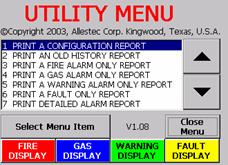
Sample printing options. Selecting the display buttons review previous alarm history events as they occurred |
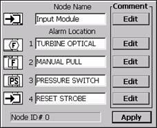
Naming 4 inputs of a node. Each of the 4 channels has an edit box to write messages for later referencing. |
 |
 |
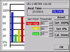
Configuring a gas input. Color bars indicate real time 4-20ma current as a percentage. Set points are also indicated. |
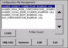
Individually created configurations can be selectively loaded or unloaded. Each of the 5 configurations represent a unique configuration that was created. Notice that a configuration containing a gas input is unloaded. Unloading a configuration disables it from alarming. |
 |
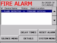 |
Operator has the choice of which incoming alarm to investigate first. Fault and warning alarms are also indicated here. If this menu is not attended to, the system will automatically execute its programming as it was set up to. |
Fire alarm menu allows several options to select during an alarm. Further occurring alarms will follow the #1 alarm indicating alarm. The scroll bar allows selective choosing of any alarms in the fire alarm window. Delay times selection brings up the timing countdown. |
 |
 |
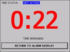
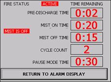
Single alarm pre-discharge. Notice the fire status indicator. The “return to alarm menu” will change to “new alarms have arrived” upon the detection of other alarms. |
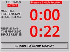
Dual release alarm with reserve backup. Notice the fire status indicator. |
 |
|
Cycle release alarm for NFPA 750. Notice the fire status indicator. |
|
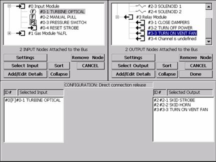 |
Configuration Sample - This image is a direct connection menu. Channel 1 of the input module is double clicked to be inserted in the selected input box. On the right side, three channels are selected for the selected output box. A unique filename is then given for this configuration and saved (as seen on previous page) in the configuration file management screen. When the turbine optical is set into alarm, all three selected outputs will simultaneously alarm. The configuration menu is required to be displayed on a standard 13" or larger monitor but is shown reduced to demonstrate the actual 5.7" diagonal touch. |
Specifications of the Onguard FG8800 Fire and Gas System
Electrical |
System Operating Voltage: |
18 - 30 VDC Redundant Power Required |
Control Panel Maximum Current: No Attached Devices Or Local Relays: |
0.78 AMPS @ 24 VDC |
8800-1060 Input Node: |
24 VDC - 20 mA Quiescent, 35 mA Alarmed |
8800-1700 4-20ma Gas Module: |
24 VDC - 14 mA Quiescent, 14 mA Alarmed |
8800-1705 Supervised Output Module (Som):
Four Relays, One Per Channel: |
24 VDC - 23 mA Quiescent, 108 mA Alarmed
7.5 AMPS, 24 VDC |
8800-1725 Relay Module: |
24 VDC - 9 mA Quiescent, 94 mA Alarmed |
Four Dry Relay Contacts, One / Channel: |
10A @ 30 VDC Resistive, 250 VAC Resistive |
Display Screen Luminous Intensity: |
350 NITS |
Terminal Strip Conductor Allowance: |
26 TO 14 GA |
Mechanical |
|
Size-Refer To Drawing In Operation Manual |
|
Control Panel Net Weight: |
13 lbs, 5.89 kg |
Environment |
|
Field Node Operating Temperature: |
0° F to 150° F
-17° C to 65° C
90% Humidity Non-Condensing |
Control Panel Operating Temperature: |
32° F to 130° F
0° C to 55° C |
Packaging And Exposure: |
NEMA 1 |
Onguard FG8800 Fire and Gas System Components
|